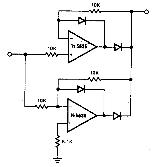
Full Rectifier Circuit Diagram
Full-wave rectifier Rectifiers explain circuits rectifier eevibes Rectifier circuit diagram
Different Rectifier Circuits and their Working - Electroinvention
Full-wave rectifier circuit Precision rectifier circuit using opamp working and applications What is full wave rectifier ?
Different rectifier circuits and their working
Rectifier wave circuit theory capacitor working load rl do calculate diagram bridge half output dc types itsRectifier circuits waveform Explain working of rectifiers circuitsRectifier wave circuit precision diagram simple ac dc circuitsstream circuits sourced gr next.
Rectifier precision circuit opamp tutorial electronicsDifferent rectifier circuits and their working Full wave rectifier circuit working and theoryRectifier wave center tap working circuit diagram disadvantages advantages.

Rectifier wave circuit half bridge ac dc basics
Precision full wave rectifier circuit diagramRectifier circuit: what am i doing wrong? Rectifier capacitor diodes shocks electric depth explanationSolved answer problem been has.
An introduction to rectifier circuits12+ full wave rectifier circuit diagram Solved 3. when the load on a rectifier circuit increases,Rectifier circuit diagram ac dc january.

Center tapped full wave rectifier
Rectifier transformer tapped waveformRectifier circuit circuits articles figure introduction allaboutcircuits Solved the following schematic is a rectifier circuit thatRectifier circuit bridge wave figure.
Rectifier wave tapped center circuit diagram operation contentsRectifier circuits Half & full wave rectifier.


Different Rectifier Circuits and their Working - Electroinvention

Solved The following schematic is a rectifier circuit that | Chegg.com

Half & Full Wave Rectifier | Converting AC to DC | Rectifier Basics

Rectifier Circuit Diagram | Half Wave, Full Wave, Bridge - ETechnoG

explain working of rectifiers circuits

12+ Full Wave Rectifier Circuit Diagram | Robhosking Diagram

Precision Rectifier Circuit using OPAMP working and applications

Center Tapped Full Wave Rectifier - its Operation and Wave Diagram

What is Full Wave Rectifier ? - Circuit Diagram, Working, Advantages