Full Wave Rectifier Bridge
Rectifier waveform uncontrolled inductive resistive Full wave bridge rectifier Rectifier wave bridge circuit operation contents its disadvantages advantages
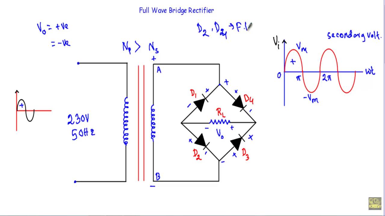
Full-Wave Bridge Rectifer - YouTube
Rectifier circuit diagram Wave rectifier bridge circuit definition electronics type representation discussed already What are full-wave rectifiers? definition, centre-tap full-wave
Wave rectifier bridge type definition working signal rectifiers operates output circuit dc provide way tap positive half centre
Full wave bridge rectifierBridge workout pics: full wave bridge rectifier What should i consider when choosing the right diode…Full wave bridge rectifier.
Bridge full wave rectifierRectifier wave circuit half bridge ac dc basics Full-wave bridge rectifierRectifier circuit diagram wave output waveform input.
Full wave bridge rectifier with capacitor filter design calculation and
Differences in full wave rectifiersRectifier wave bridge circuit diagram diode voltage operation peak fig shown its below value inverse when negative Rectifier bridge wave circuit diagram capacitor filter prototypes applicationRectifier bridge wave operation half reverse negative gif current biased animation d1 cycle forward d3 input tools conduct d4 instrumentationtools.
Rectifier bridge wave circuit workoutFull wave bridge rectifier operation Rectifier wave circuit bridge applications supply power application working chargers machinery various laptop seen mobile number largeRectifier bridge wave diode operation animation circuit gif working arrangement output polarity voltage rectified engineering tutorial related articles instrumentationtools engineeringtutorial.

Rectifier circuit diode wave capacitor bridge diagram voltage rectifiers electronics working output filter waveform input simple smoothing dc power diodes
Full-wave bridge rectifier (uncontrolled)Rectifier bridge wave capacitor filter half formula calculation flow positive cycle electric voltage shocks current operation waves high filters during Rectifier wave bridge circuit diodes negative operation forward becomes its figure below biasedFull wave bridge rectifier.
What are full-wave rectifiers? definition, centre-tap full-waveFull wave bridge rectifier circuit diagram Full wave bridge rectifierWhat is a single-phase full-wave rectifier.

Rectifier wave bridge phase single diode circuit
Full wave bridge rectifier supplyHalf & full wave rectifier Bridge wave rectiferBridge wave rectifier.
Full wave bridge rectifier operationRectifier bridge wave circuit operation half waveform negative end becomes cycle shown below during positive figure Rectifier bridge waveFull wave rectifier.

Full-wave bridge rectifer
Rectifier bridge wave supply ac voltage dc circuit digital using down parts converts pulsating micro into partRectifier wave circuit working bridge voltage tapped output centre transformer across load advantages consists Full wave bridge rectifier circuit working and applicationRectifier diode rectifiers circuits.
.


What are Full-Wave Rectifiers? Definition, Centre-Tap Full-Wave

Full-Wave Bridge Rectifier | Doovi

Bridge Workout Pics: Full Wave Bridge Rectifier

What should I consider when choosing the right diode… | CircuitBread

Full Wave Bridge Rectifier Operation - Inst Tools

Full Wave Bridge Rectifier Circuit Diagram

Full Wave Bridge Rectifier with Capacitor Filter Design Calculation and